Docker Sensor Fu on a Raspberry Pi
Tue, Mar 15, 2016For many people it comes as a surprise that one can access all the hardware of an IoT device from within a Docker container. Interestingly enough Docker is a perfect tool for managing and distributing IoT development and production environments.
To illustrate this use case we are going to create a Docker image that allows us to read the data from a temperature sensor.
To follow along you gonna need:
- a Raspberry Pi 1, 2 or 3
- our HypriotOS SD card image
- a DHT22 temperature sensor, which you can buy at Amazon
From the hardware side we need to first attach the sensor to our Raspberry Pi.
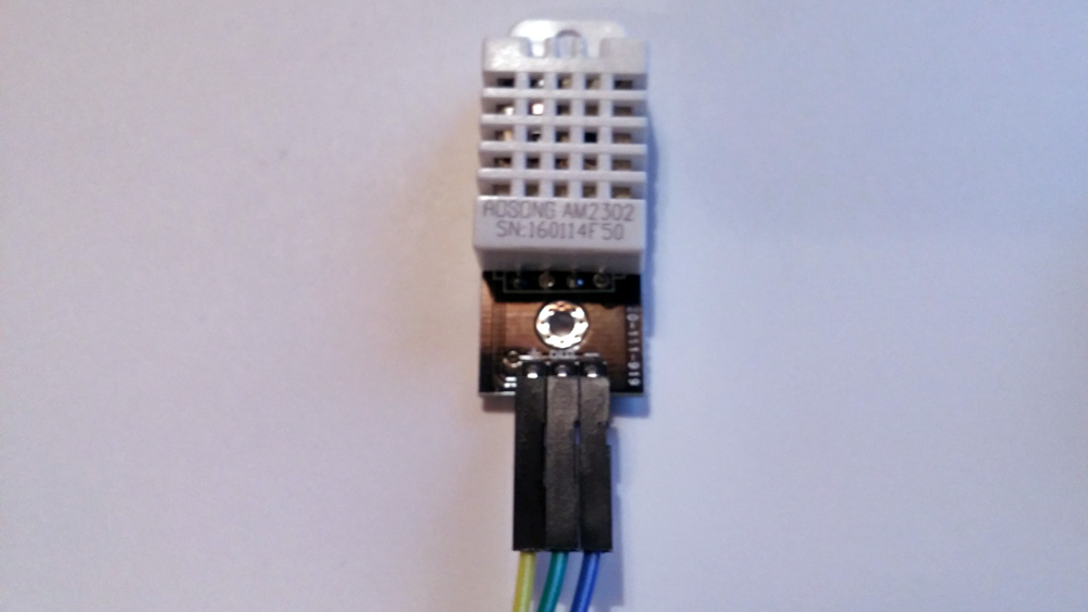
Looking at the picture of the sensor from left to right we need to attach
- the yellow cable to the 3,3V Pin of the RPi (Pin 1)
- the green cable (data) to one of the many GPIO; here it is GPIO2 (Pin 3)
- and finally the blue cable to GND (Pin 6)
The information in brackets corresponds to the pin numbers in this GPIO overview image.
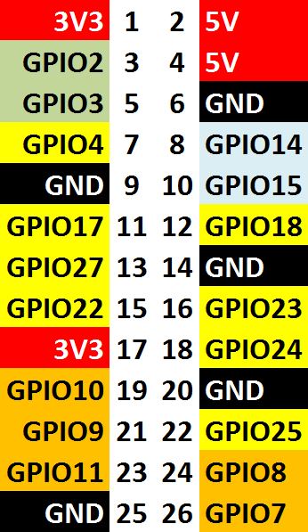
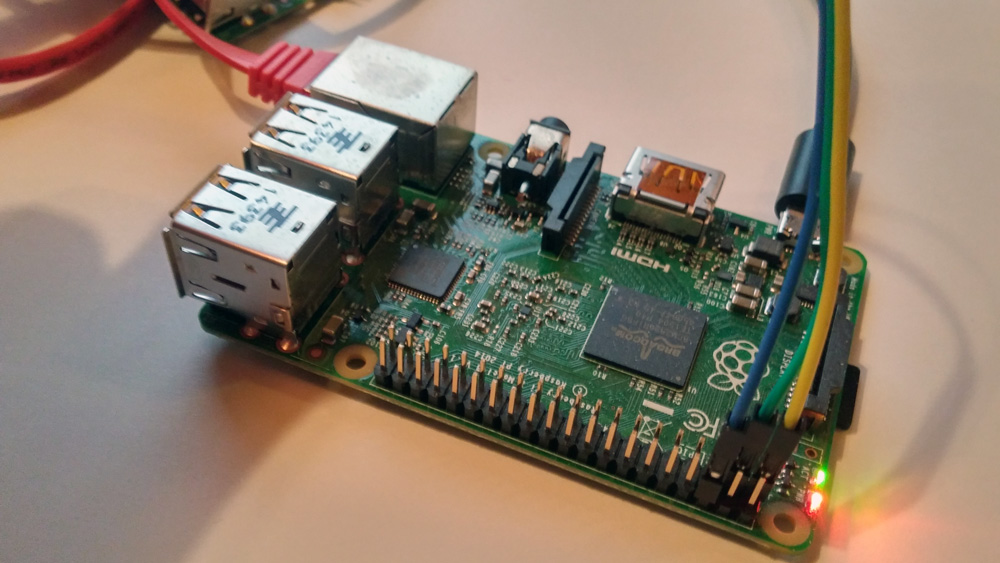
After our hardware is settled we need to look at the software side of things.
As foundation for our next steps we will use the WiringPi project. WiringPi is a library that allows to access the GPIO (General Purpose Input Output) connectors of the Raspberry Pi.
So let’s put WiringPi into a Docker image, shall we?
The Dockerfile for this looks like this:
Using this Dockerfile we can now build our image:
$ docker build -t hypriot/wiringpi:latest .
...
$ docker images
REPOSITORY                            TAG                 IMAGE ID            CREATED             SIZE
hypriot/wiringpi                      latest              599e98bd4c20        30 seconds ago      302.2 MB
Now the image has everything that we need to compile software. On top of that it also has the WiringPi libraries on board.
Next we can run this image to build the software that actually reads the sensor:
$ docker run --device /dev/ttyAMA0:/dev/ttyAMA0 --device /dev/mem:/dev/mem --privileged -ti hypriot/wiringpi bash
root@84f66e14df05:/data#
To test if we can access the GPIO’s we can run:
root@84f66e14df05:/data# gpio readall
 +-----+-----+---------+------+---+---Pi 2---+---+------+---------+-----+-----+
 | BCM | wPi |   Name  | Mode | V | Physical | V | Mode | Name    | wPi | BCM |
 +-----+-----+---------+------+---+----++----+---+------+---------+-----+-----+
 |     |     |    3.3v |      |   |  1 || 2  |   |      | 5v      |     |     |
 |   2 |   8 |   SDA.1 |   IN | 1 |  3 || 4  |   |      | 5V      |     |     |
 |   3 |   9 |   SCL.1 |   IN | 1 |  5 || 6  |   |      | 0v      |     |     |
 |   4 |   7 | GPIO. 7 |   IN | 1 |  7 || 8  | 1 | ALT0 | TxD     | 15  | 14  |
 |     |     |      0v |      |   |  9 || 10 | 1 | ALT0 | RxD     | 16  | 15  |
 |  17 |   0 | GPIO. 0 |   IN | 0 | 11 || 12 | 0 | IN   | GPIO. 1 | 1   | 18  |
 |  27 |   2 | GPIO. 2 |   IN | 0 | 13 || 14 |   |      | 0v      |     |     |
 |  22 |   3 | GPIO. 3 |   IN | 0 | 15 || 16 | 0 | IN   | GPIO. 4 | 4   | 23  |
 |     |     |    3.3v |      |   | 17 || 18 | 0 | IN   | GPIO. 5 | 5   | 24  |
 |  10 |  12 |    MOSI |   IN | 0 | 19 || 20 |   |      | 0v      |     |     |
 |   9 |  13 |    MISO |   IN | 0 | 21 || 22 | 0 | IN   | GPIO. 6 | 6   | 25  |
 |  11 |  14 |    SCLK |   IN | 0 | 23 || 24 | 1 | IN   | CE0     | 10  | 8   |
 |     |     |      0v |      |   | 25 || 26 | 1 | IN   | CE1     | 11  | 7   |
 |   0 |  30 |   SDA.0 |   IN | 1 | 27 || 28 | 1 | IN   | SCL.0   | 31  | 1   |
 |   5 |  21 | GPIO.21 |   IN | 1 | 29 || 30 |   |      | 0v      |     |     |
 |   6 |  22 | GPIO.22 |   IN | 1 | 31 || 32 | 0 | IN   | GPIO.26 | 26  | 12  |
 |  13 |  23 | GPIO.23 |   IN | 0 | 33 || 34 |   |      | 0v      |     |     |
 |  19 |  24 | GPIO.24 |   IN | 0 | 35 || 36 | 0 | IN   | GPIO.27 | 27  | 16  |
 |  26 |  25 | GPIO.25 |   IN | 0 | 37 || 38 | 0 | IN   | GPIO.28 | 28  | 20  |
 |     |     |      0v |      |   | 39 || 40 | 0 | IN   | GPIO.29 | 29  | 21  |
 +-----+-----+---------+------+---+----++----+---+------+---------+-----+-----+
 | BCM | wPi |   Name  | Mode | V | Physical | V | Mode | Name    | wPi | BCM |
 +-----+-----+---------+------+---+---Pi 2---+---+------+---------+-----+-----+
So far so good.
Now we need to clone the source of our sensor reading software:
root@84f66e14df05:/data# git clone https://github.com/technion/lol_dht22
root@84f66e14df05:/data# cd lol_dht22
To compile the lol_dht22 software we do the usual ./configure && make:
root@84f66e14df05:/data/lol_dht22# ./configure
...
root@84f66e14df05:/data/lol_dht22# make
This should produce a small executable that we can now test.
If you followed the wiring instructions above closely you should now be able to read the temperature:
root@84f66e14df05:/data/lol_dht22# ./loldht 8
Raspberry Pi wiringPi DHT22 reader
www.lolware.net
Humidity = 34.00 % Temperature = 22.80 *
Awesome. We just have been accessing the hardware sensor that is attached to our Pi from inside a Docker container.
So why is this so exciting? Well, it basically allows us to deploy our sensor reading software easily and reliably to every device that is running a Docker Engine. No installation hassle. No dependency hell.
For that we need to extend our Dockerfile and add
RUN git clone https://github.com/technion/lol_dht22
RUN cd lol_dht22 && ./configure && make && mv ./lol_dht22 /usr/local/bin
The finished file looks like this:
After rebuilding the image with this updated Dockerfile we can now run
$ docker run --device /dev/ttyAMA0:/dev/ttyAMA0 --device /dev/mem:/dev/mem --privileged -ti hypriot/wiringpi /loldht 8
Raspberry Pi wiringPi DHT22 reader
www.lolware.net
Data not good, skip
Humidity = 35.00 % Temperature = 22.00 *C
and it just works™.
The finished image can be found at the Docker Hub.
That’s it. As always, use the comments below to give us feedback and share this post on Twitter, Google or Facebook.
Govinda @_beagile__
comments powered by Disqus